How to Open a Sun SPOT
Before we run anything on the Sun SPOT, let's take a look at one of them. You should have three Sun SPOTs. One is a basestation and two are free-range Sun SPOTs.
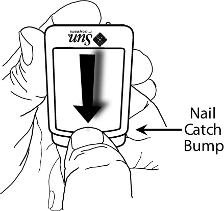
Pick up one of the free-range Sun SPOTs. There is a lid on the Sun SPOT, sometimes called a Sun roof. You will need to take the lid off to get at some of the switches and LEDs. To open the lid, press firmly on the lid, down and back, on the edge of the lid near the small raised dot. You can think of that small-raised dot as the fingernail-catching dot. The closer to the edge that you press, the easier the lid will open. See the illustrations below:
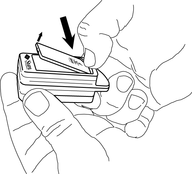
The opposite end of the lid will pop up. Grasp that opposite end to remove the Sun SPOT lid.
Now that you have opened it, you can see the LEDs and switches on the sensor board.
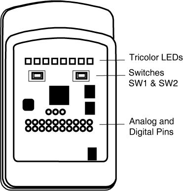
These are under Java program control, so they will act differently, depending on the application that is running. That fin at the top of the Sun SPOT is the radio fin housing the antenna for the wireless communication.
If you tilt the Sun SPOT so that the fin is away from you, you will see the Control Button.
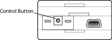
The Control Button is used to reset the Sun SPOT, to put it to sleep, and to wake it up. If the Sun SPOT is asleep, clicking once, briefly - just a tap - on the Control Button will wake the Sun SPOT up. You may have to press hard, but you don't have to press long. If the Sun SPOT is awake, clicking once on the Control Button will reset the Sun SPOT and restart whatever program it was running. Pressing the Control Button down and holding it down for five seconds will put the Sun SPOT to sleep. Let's try it out:
- To turn on the Sun SPOT: Pick up one of the free-range Sun SPOTs. Press the Sun SPOT Control Button firmly and briefly, just a tap. You have just turned it on. You should see the LED to the right flicker green for about two seconds. That's the Sun SPOT looking to see if it is connected to a host workstation. Some of the LEDs on the top should also light up because there is a demo on the Sun SPOT that turns them on.
- To turn off the Sun SPOT: Press the Control Button and hold it down for about five seconds. The LED to the left should flash red twice then go dark. You have just turned the Sun SPOT off.
- To reset the Sun SPOT: Turn on the Sun SPOT so the preloaded demo is running again. To reset a running Sun SPOT, just tap the Control Button again. The LEDs on the right will flicker green for about two seconds.
That's it! You have mastered the Sun SPOT Control Button.
NOTE: If the free-range Sun SPOT does not boot, if the LED to the right doesn't flicker when you tap the Control Button, the Sun SPOT probably needs to charge its battery. To charge a Sun SPOT battery, attach the Sun SPOT, using the supplied USB cable, to the USB port on a working computer. The USB power will fully charge the Sun SPOT in approximately three hours.
Here is a little more detail on the LEDs that are on either side of the Sun SPOT Control Button.
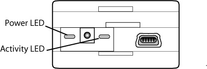
Those LEDs can be controlled by Java programs on the Sun SPOT, but in ordinary circumstances, they are controlled by the operating environment on the Sun SPOT. The LED on the left will tell you about the power status on the Sun SPOT. Here are its most important signals:
| Power LED Signal | Meaning |
| Three red flashes | Powering down |
| Slowly alternate between bright and dim green | Charging from USB; CPU active |
| Slowly alternate between dim green and off | Charging from USB; CPU asleep |
| Steady dim green | Attached to USB, fully charged; CPU active |
| Steady dim red | Battery low. |
| One short green flash | Resetting, restarting program. |
| One bright green pulse, sharp on, soft off |
Powering up
|
The LED on the right is under application control. If that behavior is not changed, the system programs will use it to tell you about the communication status of the Sun SPOT. Here are its most important signals.
| Activity LED Signal | Meaning |
| Rapidly flash green |
Searching for the host workstation on the USB connection
|
| Flash green | Packets being received from the host workstation |
| Flash red | Packets being sent to the host workstation |
| Blink green twice every 12 seconds | Normal functioning as a basestation. |
You've taken the basic tour of the Sun SPOT. Now we'd like you to try some demos.