Displaying the Sensor Panel
As you did for the Sawtooth demo, right click on the virtual Sun SPOT, and from the popup menu choose Display Sensor Panel. You will hear a “whoosh” sound if your sound system is enabled. A tabbed panel appears to the left, perhaps outside the grid. With your mouse, move the virtual Sun SPOT to the right until the entire sensor panel is visible.
Right click again on the virtual Sun SPOT to pop up a menu, but this time choose Run MIDlet > SensorChecker.
Light and Temperature
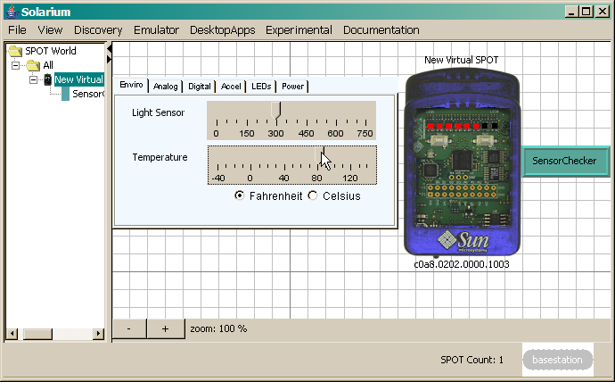
The SensorChecker demo starts with the LEDs indicating in white the light level read from the virtual Sun SPOT's light sensor. For a virtual Sun SPOT this level can be set manually using the Light Sensor slider. The numbers indicate the luminance in terms of raw sensor readings. These numbers can be approximately converted to Lux (lx) by multiplying them by 2.
Using your mouse, move the Light Sensor slider back and forth. For higher readings more LEDs will light up.
The SensorChecker application prints a message when the light level goes below 10 or above 740. To see this, open up a print window by right-clicking on the virtual Sun SPOT; from the pop-up menu, choose Display Application Output > In Internal Frame. Now if you move the slider to the extreme left or right, a message is displayed. The program waits two seconds after printing a message before it will check again.
Click the gray rectangular switch located on the left, below the second LED. You will hear a “click” sound if your sound system is enabled. The LEDs will change to red and show the reading of the virtual Sun SPOT's temperature sensor.
Using your mouse, move the Temperature slider back and forth, as shown in the image below. More LEDs will light up as you increase the temperature. You can select whether the Temperature slider displays in degrees Celsius or Fahrenheit.
Analog and Digital Pins
In the Sensor Panel, click the Analog tab. It shows six vertical sliders representing electrical input from the Sun SPOT's six analog pins. Click the left switch again. All LEDs turn from red to black, because they represent the setting of the A0 slider, which by default starts at zero.
Using your mouse, move the A0 slider upwards to turn the LEDs green. Sliders A1 to A5 do not affect LED color in the SensorChecker demo.
In the Sensor Panel, click the Digital tab. It shows radio buttons representing the state of the five digital input/output pins D0 through D4 and the four high-current output pins H0 through H3. For the SensorChecker application pin D0 is configured as an output pin, so it cannot be set in the Sensor Panel. Pins D1 through D4 are configured as inputs that the radio buttons can set. The SensorChecker application detects changes to the value of pin D1 and sets pin D0 to have the same value as pin D1. Try changing the value for pin D1 and notice how the value of pin D0 changes to match. The program also sets one of the high-current pins to high depending on which input it is reading. Each time you click the left switch a different high-current pin will be set high.
Accelerometer
Click the gray rectangular switch below the second LED once again. Half of the LEDs turn blue. This is because your virtual Sun SPOT is now measuring its acceleration and it is at rest!
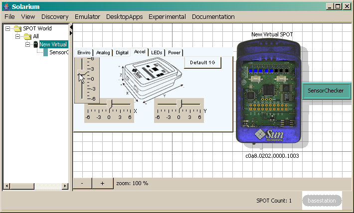
In the Sensor Panel, click the Accel(eration) tab. This tab of the sensor panel displays a drawing of the Sun SPOT, with sliders controlling the sensed acceleration force in three directions along X, Y, and Z axes. Using your mouse, move the leftmost slider for the Z axis up and down. All the blue LEDs illuminate with maximum upward acceleration. The LEDs are all black with maximum downward acceleration. Sliders on the X and Y axes do not affect LED color.
After moving all three sliders away from the zero position, click the Default 1G button. This resets X and Y to zero, and the Z axis to one. This is because the earth's gravity generates a force equivalent to moderate upward motion.
Virtual Switches and LEDs
In the Sensor Panel, click the LEDs tab. This panel shows the same colors as the virtual Sun SPOT: five blue squares if you left the Z axis acceleration slider at 1G.
Click the SW2 checkbox. In the Sun SPOT picture, look at the rectangle switch underneath the seventh LED. It turned black, indicating SW2 is down. Click the SW2 checkbox again. The black rectangle turns gray. Now click the second switch in the picture to toggle the SW2 checkbox, and make a double-click noise if your sound system is enabled. On a physical Sun SPOT, the switches have both down and up positions, but usually a feature is toggled by cycling through both.
Click the SW1 checkbox twice. Repeat this double-clicking four times. With each two, down and up, The LEDs change color in this order:
- white to indicate light
- red to indicate temperature
- green to indicate analog input on A0
- blue to indicate Z axis acceleration
The G and R squares on the far right display the state of the Green and Red Activity LEDs physically located on the Sun SPOT's bottom side. They are black because the SensorChecker demo does not use them.
Managing the Sun SPOT Battery
A physical Sun SPOT contains a sophisticated power management system with a lithium-ion battery that you can recharge with USB power.
In order to save battery power, you can write programs that put the Sun SPOT to sleep, and wake it up periodically or when some event occurs. This approach to power management can make the battery charge last almost as long as if the Sun SPOT were powered off.
Select the Power tab of the Sensor Panel, and click the USB Power Connected check box. The Battery voltage slider moves immediately to 4500 millivolts, the specified minimum for bus-connected USB, although in practice 4750 millivolts is common.
The SensorChecker demo uses neither the Battery Voltage nor the Charge Rate slider. With other applications you can use them to simulate battery level and discharge under theoretical field conditions.
Ending SensorChecker and Exiting Solarium
To exit the SensorChecker demo, right click on the teal SensorChecker flag and choose Exit.
To hide the sensor panel, right click on the blue virtual Sun SPOT and from the pop-up menu choose Hide Sensor Panel.
Quit Solarium by clicking File > Exit.